Motor Controls Wiring Diagram
View Motor Controls Wiring Diagram Background. Wiring diagrams, sometimes called main or construction diagrams, show the actual connection points for the wires to the components and terminals of the controller. Stepper motor wiring diagram elegant ponent series circuit diagrams.
Pwm, or pulse width modulation is a technique which allows us to adjust the average value of the voltage that's going to the electronic device by turning you can use any arduino board for this project.
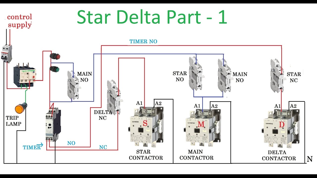
18 696 просмотров 18 тыс. For specific leeson motor connections go to their website and input the leeson catalog # in the review box, you will find connection data, dimensions, name plate data, etc. Other variations shown in this section may appear more. Wiring diagrams and control methods for three phase ac motor.

0 Response to "Motor Controls Wiring Diagram"
Post a Comment