39+ Motor Rpm Meter Circuit Diagram PNG. Rest of the things are explained very well in above picture. This is the circuit diagram of digital tachometer / digital rpm meter which can be used for cars or motorcycles with 2 and 4 stroke petrol engines with any number of.
Introduction to Digital Tachometer Circuit Working with ... from www.elprocus.com So we have to measure how many times a particular point on the rotor undergoes a full rotation within a minute. It's used as a measure of revolution of the motor, the most intuitive formulation is that how fast the motor will first you should know how many factors impact the value of rpm? This is all about the basic requirement.
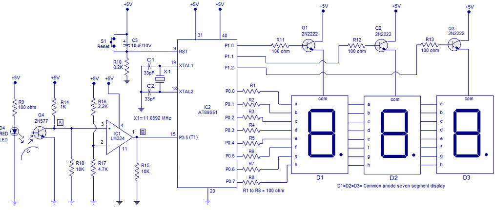
Download circuit diagram and programming:
String led circuit diagram constant current power supply. This triac based ac motor speed controller circuit is designed for controlling the speed of ac motors like drill machines, fans, vacuums, etc. Rpm the full name is revolution per minute. The figure shows the circuit diagram of two stage stepper motor driver.

0 Response to "Motor Rpm Meter Circuit Diagram"
Post a Comment